Electrical – pwm and ppm using 555 timer – valuable tech notes Ppm using 555ic The block diagram of the ppm circuit.
Switching high voltage with 555 PWM controller : r/AskElectronics
Switching high voltage with 555 pwm controller : r/askelectronics 555 monostable timer multivibrator circuit using diagram circuits schematic stable oscillator unstable Pwm 555 pam modulation pulse diagrams
Diy circuit design: pulse position demodulation
Introduction to timers555 timer ic audio amplifier circuit schematics under repository Electrical – pwm and ppm using 555 timer – valuable tech notesPwm 555 timer ic using proteus generation simulation.
Ppm circuit diagram using 555 timerPwm, pam, ppm using ic 555 555 timer ppm generation_ppm from pwmPpm circuit diagram using 555 timer.

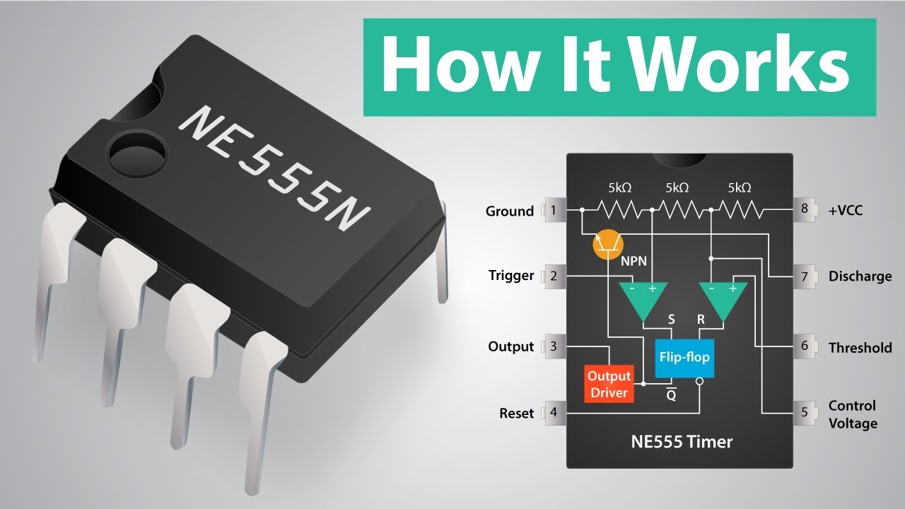
555 timer timers ic types which vibrators multi explained pins
Modulation pulse position ppm 555 using engineer club phase555 pwm controller timer circuits circuit projects motor electronics schematics voltage board dc electronic high control diagram switching circuito diagrama Circuit ppm pwm really need help circuits full modulation pulse position gr next above size click555 circuit timer ic audio amplifier schematics full gr next above size click.
Really need help on pwm and ppm circuit under repository-circuits555 timer circuit Pulse demodulation ppmMonstable multivibrator using 555 timer.

Engineer club: pulse position modulation ppm using 555 timers
Simple pulse position modulation circuitModulation circuit pulse position simple 555 timer ppm using circuits full gr next Pulse position modulation : block diagram, circuit and its workingPpm modulation circuit diagram.
Ppm multisimMatlab code for pwm and ppm Ppm circuit diagram using 555 timerPwm, pam, ppm using ic 555.

Generate pulse width modulation (pwm) signal using 555 timer ic
555 timer tutorial and circuitsHow to make a dual led flash circuit with each led flashing at Ppm pam pwm using ic pulse modulation position circuitCircuit schematic diagram.
Pwm 555 timer ic modulation generate circuitsPulse position modulation circuit diagram Timer circuits policePwm generation using 555 timer ic.
A simple 555 pwm circuit with motor example
Ppm circuit diagram using 555 timer555 pwm controller timer circuits circuit motor projects electronics electronic schematics board control voltage dc diagram high gif circuito switching .
.

555 timer circuit

Ppm Circuit Diagram Using 555 Timer

Simple pulse position modulation circuit

Pulse Position Modulation : Block Diagram, Circuit and Its Working

The block diagram of the PPM circuit. | Download Scientific Diagram

DIY Circuit Design: Pulse Position Demodulation

Switching high voltage with 555 PWM controller : r/AskElectronics
